Maintenance for BNMR-Oxford Cryostat
Date:
Monday, October 7, 2019
Synopsis:
High-T Upgrade Finished
Equipment/Beam Line:
Description:
- Oct 2:
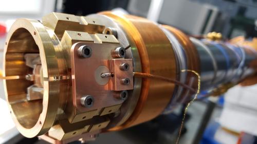
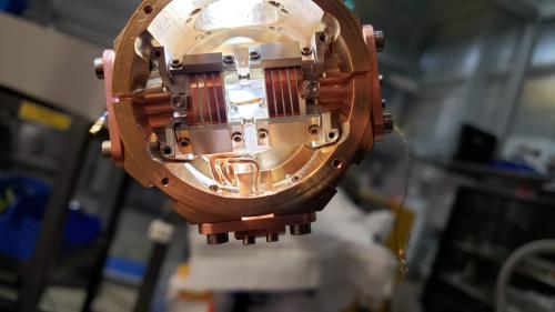
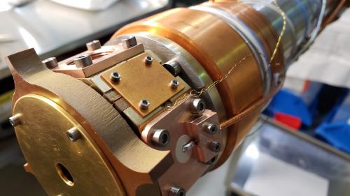
- 90 degree connections to RF coils soldered.
- PEEK spacers trimmed with scalpel. Note that now each spacer is unique to the solder job on each pin.
- Titanium screws from the clamps on the old RF flanges moved to the new ones. The old screws are replaced with Aluminum for durability in storage.
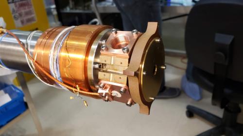
- New RF flanges installed. The left clamp on the RF coil is somehow smaller in diameter than the right one. The same pin has a much harder time fitting into the ring clamp on the left than the right. Checked that the clamp opening was not obstructed. With some effort it is possible to fully insert the pin.
Note that we clamped directly to the braid on the RF coax. This is susceptible to twisting, and the SMA connectors to the long portions of the coax have a tendency to do just this during their initial few turns. No pressure is applied to the dielectric.
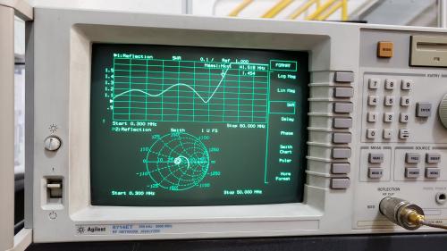
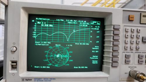
- Network analyzer used to measure circuit performance.
- New circuit has a SWR of 1.450 at 41.208 MHz
- New cables, connected together without the coil end section, has a SWR of 1.043 at 41.026 MHz (peaking at 1.2)
- New antenna installed. Connected to output marked with a "P" on exterior.
- Verfied that thermometry circuits are unharmed.
- Oct 3:
- Cleaned grease and applied boron nitride to sample mounting flange.
- Oct 4:
- Teflon concentricity spacer replaced with Kapton version. Needed some filing to get it to fit.
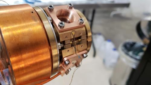
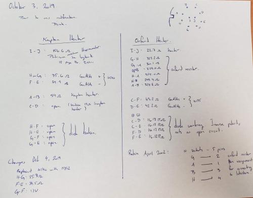
- Thermometer locations exchanged in order for the cables to reach. Broken thermometer replaced with 11832 (right side). The left side is now 10175.
- The new thermometer leads were crimped. The negative terminal (green) missed one of the cables so this was soldered in.
- The labels on the cryostat have been updated. Connections verified. Lead resistance is about the same, H-G = 35.3 ohm and F-E = 34.5 ohm, and the diode voltage is 1.1 V.
- Teflon thermometer mounts replaced with Kapton versions. These do not leave space for the wires to enter the crimps as before, therefore the wires now exit through a small cutout near the side of the capping plate.
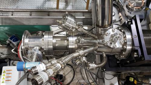
- Reassembled cryostat, installed in beam line.
- 10 cm spacer installed in front of re-entrant tube. There is no copper spring spacer in one of the copper channels on the re-entrant tube exterior.

